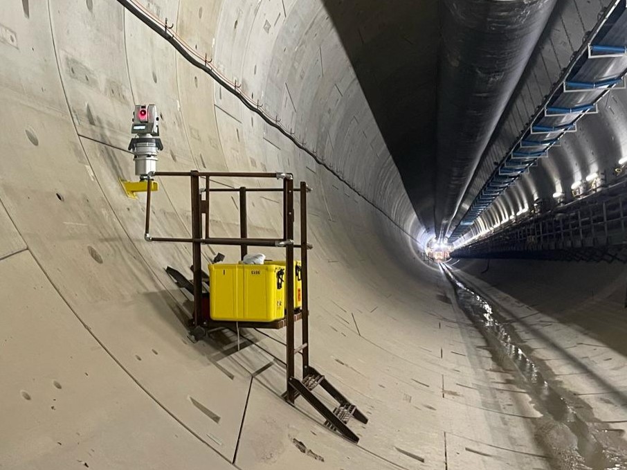
STAR*NET is often used to compute control for tunneling. Tunneling engineers combine total station, leveling and gyrotheodolite input into a single network.
A gyrotheodolite is a unique type of sensor which combines a gyroscope and a theodolite. It is invaluable in the tunneling setting, as it is used to derive an azimuth from the daily rotation of the earth around the polar axis and can independently verify the accuracy and precision of traverse data before a tunnel breaks through.
 |
Here are some important matters to consider when combining gyroscope data in a STAR*NET adjustment:
Inputting Gyroscopic Observations
Inputting a gyroscopic measurement is simple, just use a "B" record as explained below:
Example of a B record
| B |
Bearing or Azimuth |
| Format |
B From-To Bearing or Azimuth [Standard Error] ['Description] |
Simple input of 12 degrees 12 minutes 34 seconds:
B stat1-stat2 12.1234 'description
or
B stat1-stat2 12-12-34 'description
Converting Astronomic Azimuth to Grid Azimuth:
The output of a gyrotheodolite is derived from an astronomic azimuth. Most STAR*NET adjustments are performed in a grid reference frame so input must be corrected for:
- Difference between astronomic and geodetic azimuth (Laplace and deflection of the vertical corrections)
- Difference between astronomic and geodetic azimuth (coordinate system convergence)
In practice this conversion is usually accomplished by performing a gyroscopic survey of known above ground points, but this can also be accomplished or verified using the following:
Converting Astronomic Azimuth to Geodetic Azimuth
The azimuth reported by a gyroscope is calculated from the polar axis so is an astronomic azimuth. STAR*NET always computes an adjustment in the grid framework so astronomic azimuths must be corrected before input in STAR*NET. Derive a Geodetic Azimuth from Astronomic by applying a Laplace equation and accounting for deflection of the vertical. STAR*NET does not have tools that will perform this computation.
Converting Geodetic Azimuth to Grid Azimuth by correcting for Convergence
STAR*NET has features that allow you to reference or apply convergence at a station. This correction can be applied before input, or by applying an inline option.
Correction Method 1: Correcting Convergence before input:
You can use STAR*NET or a variety of other tools to compute the convergence value:
1. Open a project which has been assigned a grid coordinate system
2. Before we start, adjust your listing options in project settings:
Uncheck "Show Azimuths as Bearings" so that Az/Bearing input is displayed as angle right values rather than Compass quadrants
Check on "Convergence and Grid Factors"
3. Run the adjustment
4. In the listing, find "Convergence Angles (DMS) and Grid Factors at Stations" and note the convergence angle at the "From" station:
Convergence ------- Factors -------
Station Angle Scale x Elevation = Combined
merid 0-00-00.00 0.99960000 0.99998433 0.99958434
stat1 0-45-57.88 0.99966308 0.99998433 0.99964742
5. Subtract the convergence angle from the geodetic azimuth before inputting in STARNET.
Correction Method 2. Use .MEASURED BEARING inline:
This method does not require computing convergence, simply assign a coordinate system to your project
1. Before entering any B records with geodetic azimuths, input:
.MEASURED BEARING
2. After entering a geodetic azimuth, turn off the correction for convergence by inputting:
.GRID BEARING
ie:
.MEASURED BEARING
B merid-1 12-12-34 'description
.GRID BEARING
Assigning Instrument Standard Error for Gyroscopic Observations
A gyrotheodolite is a precision instrument which requires regular calibration. The calibration document will contain a standard deviation value that will be used for weighting gyroscopic observations. In the example calibration document below a standard deviation of less than 2 milligons is listed, this is the value to be used for weighting:
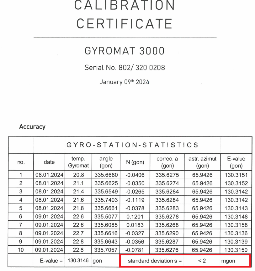
NOTE: in this example the standard deviation of less than 2 milligons (6.48 seconds) is quite pessimistic when compared to a manual computation of the standard deviation of the listed population. Consult with the agency deploying the gyroscope for advise on realistic weighting values to apply.
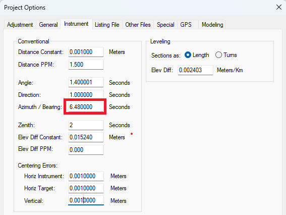
Weighting Method 1: Weight in Project Options:
If there is only a single Azimuth input in the project, or if you use the same gyroscope for all azimuth input, you can enter the calibration value in the "Bearing" section of the project options. In the example below, 2 mgon was converted to seconds and input:
Weighting Method 2: Weight with an inline entry:
If there is going to be more than one gyroscope input during your campaign, it may be wise to weight the gyroscope input inline to allow for redeployment of the gyro at different times and possibly with different calibration settings. In the example below we have added a standard deviation of 6.48 seconds following the azimuth input:
B merid-1 12-12-34 6.48 'description
Accounting for GONS
Finally, while most STAR*NET projects are conducted using degrees, minutes and seconds as the angular unit, contractors that deploy gyros frequently report results as gons or grads. You can convert the gons value to degrees, minutes and seconds, or use the inline .UNIT to tell STAR*NET to reinterpret the input. The example below shows how to input GONS in a DMS project:
.UNIT GONS
B merid-1 13.5660491203 2.0 'description
.UNIT DMS
James Johnston
Comments